Skip to content
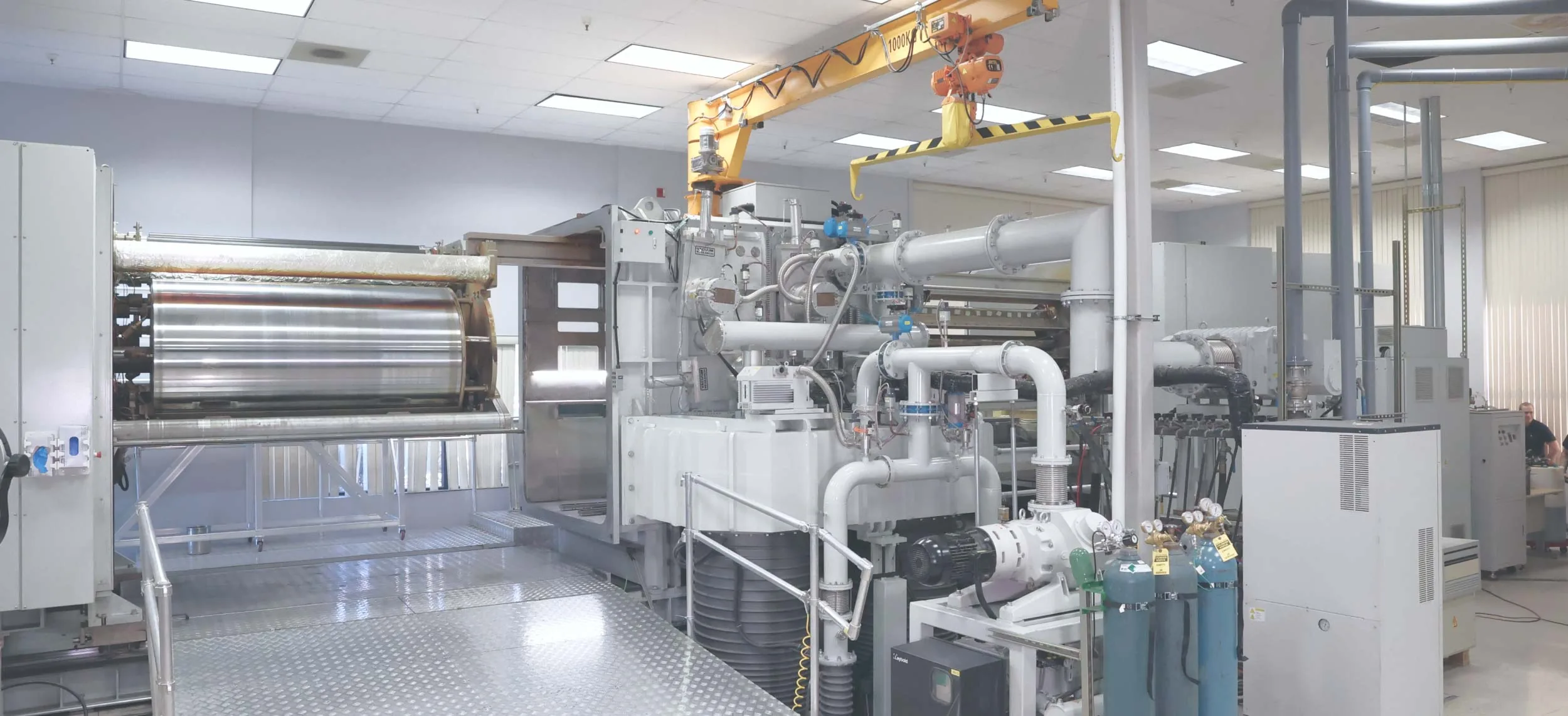
A NanoLam vacuum deposition machine: the process drum, the vacuum chamber and its pumps and piping
NanoLam™ Technology

Thousands of nano-thick thermoset dielectric layers and metal electrodes are deposited together in one proprietary process to form a nanolaminate structure, which is processed to create super-high energy density capacitor products capable of operating in the most extreme environments.

Making NanoLam™ Capacitors

01 / 03

NanoLam™ Layer Deposition

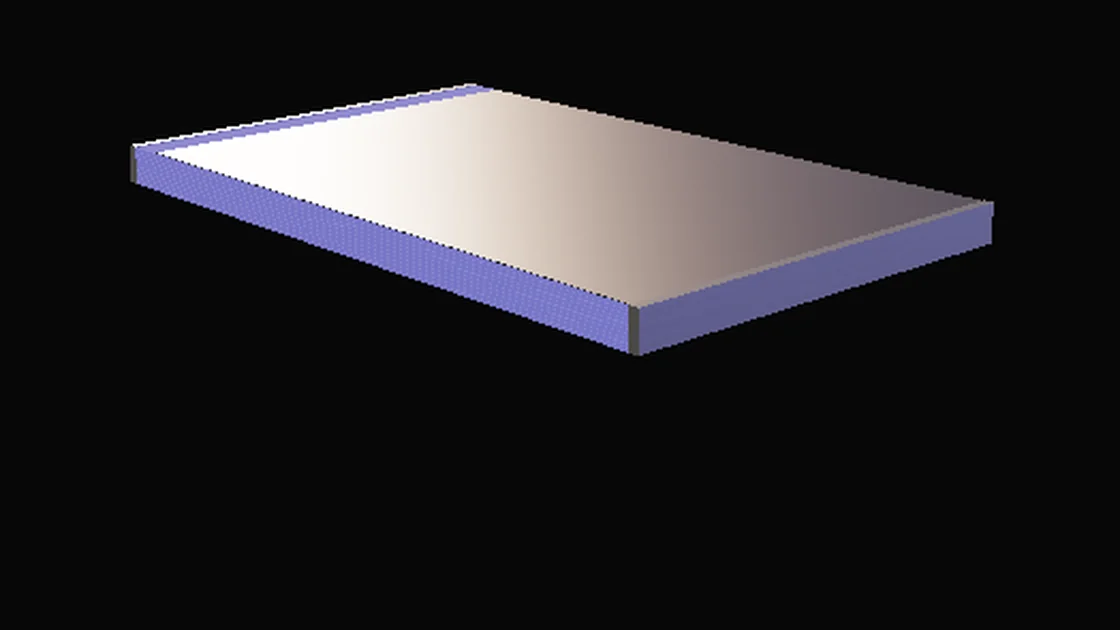
Thousands of nano-thick dielectric layers are formed with alternating electrode layers to create a self-supported Nanolaminate.

NanoLam™ dielectrics are formulated for self-healing, low ESR and high-temperature operation: designed to operate at 140°C, with exposure up to 200°C.
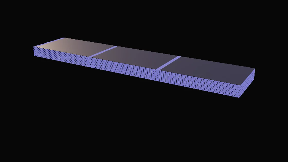
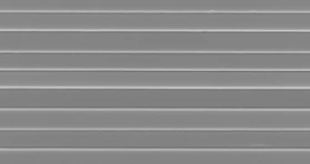
Illustration: a wide sheet of alternating electrode and glowing dielectric layers
Scanning electron micrograph of NanoLam layers: evenly spaced thin bright lines on a grey ground
NanoLam™ layers · SEM ×11,000
02 / 03

NanoLam™ Element Termination and Testing

The Nanolaminate material is diced and terminated to create NanoLam™ elements, the fundamental building blocks of all NanoLam™ capacitors.

Every NanoLam™ element is tested for capacitance, ESR and dissipation factor, among other checks.

Illustration: one diced element with sprayed metal on both ends
A long NanoLam element with a copper-coloured face lying on a bed of hundreds of small NanoLam elements
NanoLam™ elements, large and small
03 / 03

NanoLam™ Block Assembly

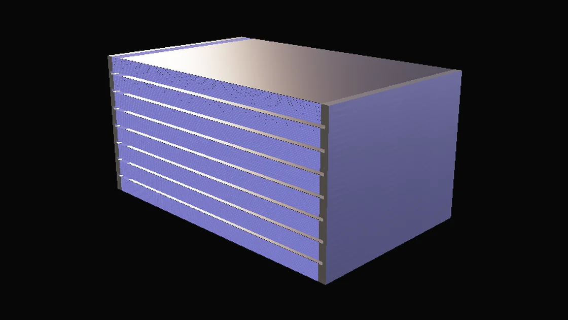
NanoLam™ elements are stacked and connected in parallel to create blocks, which are then terminated and packaged to make a finished NanoLam™ capacitor.

Illustration: eight elements stacked into a block, joined by sprayed metal along both ends
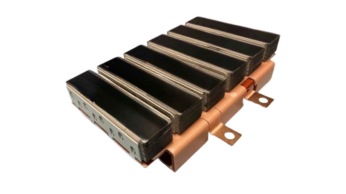
Six NanoLam blocks laser welded side by side to a copper-coloured laminated busbar with two bolt tabs
NanoLam™ blocks laser welded to a laminated busbar
Process

Dielectric formation and electrode deposition happen in the same vacuum, in the same machine, in one continuous pass. Nothing is handled between layers.

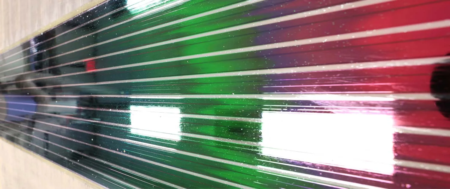
  1. Coloured metallised NanoLam film on the process drum of the deposition machine
    Nanolaminate Composite
    01

    Integrated

    Liquid resin (the dielectric) and metal wire (electrodes) enter the NanoLam™ machine — a self-supported nanolaminate material with thousands of sub-micron layers is the result.

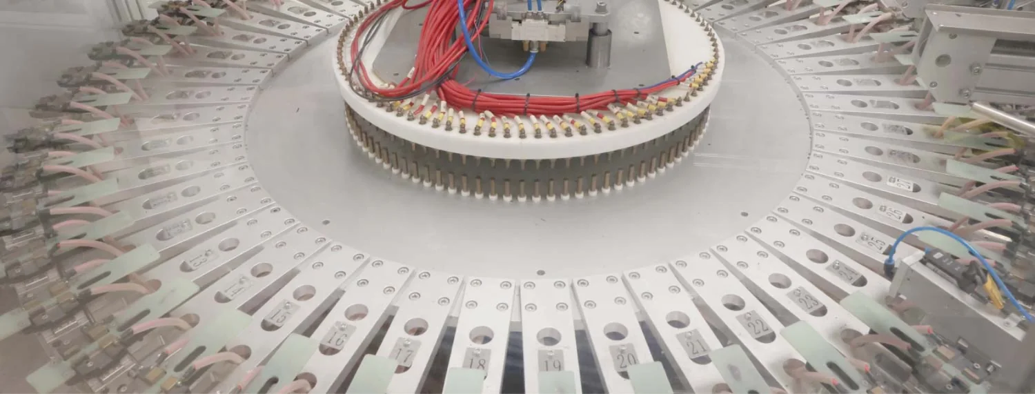
  2. A ring of test fixtures around a carousel of NanoLam elements
    Automated Element Testing
    02

    Traceable

    The nanolaminate is processed to create NanoLam™ elements — functioning, unpackaged, capacitors. Every element is tested before incorporation into a packaged capacitor.

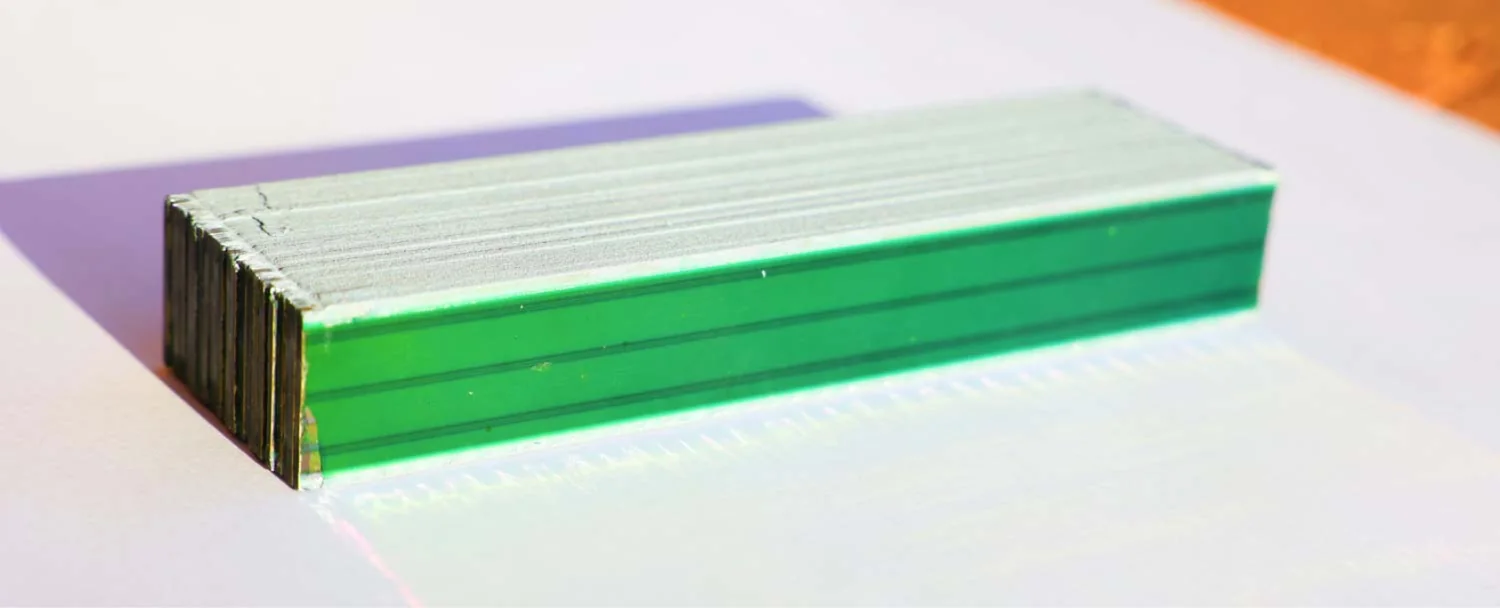
  3. A stacked NanoLam block with green edges on a white surface
    NanoLam™ Block
    03

    Scalable

    NanoLam™ elements are stacked and connected in parallel to form a “block.” There is no limit to how many elements/blocks can be used in the final capacitor.

NanoLam™ Thermoset Dielectric

Polypropylene, PEN, PPS and polycarbonate are thermoplastics. Polymer chains loosen (or melt) as temperatures rise, which reduces dielectric strength — the capacitor has to be voltage derated.

NanoLam™ dielectrics are based on cross-linked thermoset acrylates. Polymer chains are locked in place and do not loosen or melt as temperatures rise — NanoLam™ capacitors hold full rated voltage up to 140 °C.

Polymer chains in a thermoplastic film and in a NanoLam thermoset, from 75°C to 140°CLeft: long chains lying side by side, held only by weak attraction, which slide apart from 85°C and let go by 105°C, then pool. Right: chains joined by crosslinks into one network, which flexes when heated but holds its shape to 140°C. Derating from manufacturer data: BOPP 14 percent at 105°C; at 125°C HC-BOPP 29, PEN 25, PPS 25 and polycarbonate 60 percent; NanoLam 0 percent up to 140°C.
Polymer chains at the molecular level, with derating figures from manufacturer data
Stability and Safety

Most ceramic capacitors use ferroelectric dielectrics. Capacitance can vary greatly depending on voltage, temperature, and frequency. Ceramic capacitors are also brittle and can fail short — a risk that can translate into severe voltage derating. This is not the case with NanoLam™ capacitors. In addition to their self-healing, fail-open behavior, NanoLam™ capacitors are stable on bias and exhibit little change in capacitance as a function of temperature and frequency.

DC bias±0.0%

%ΔC on Bias

Capacitance does not change as a function of voltage. What you specify at zero volts is what the circuit sees at rated voltage: no bias derating, no oversizing.

Capacitance change against DC biasLine chart of capacitance change in percent against DC bias as a percentage of rated voltage. NanoLam stays flat at zero. An X7R multilayer ceramic capacitor falls steadily, to about minus 80 percent at rated voltage.0−20−40−60−800255075100ΔC, %DC bias, % of rated voltageNanoLam™X7R MLCC
Temperature±5%

%ΔC < −55°C to 140°C+

Capacitance varies ±5% across temperature ranging from cryogenic to > 140°C, compared to ceramics that can see fluctuations of as much as ±15%.

Capacitance change against temperatureLine chart of capacitance change in percent against temperature from minus 55 to 140 degrees Celsius. ThermoLink rises gently from about minus 1 percent to about plus 2 percent. An X7R multilayer ceramic capacitor swings between about minus 10 and plus 2 percent up to 125 degrees.+10+50−5−10−50050100ΔC, %Temperature, °CX7R MLCCThermoLink™
  • Fail Open Mode

    NanoLam capacitors do not short. Failure mode is capacitance loss over time.

  • Tough, Not Brittle

    Ceramic capacitors crack under board flex and thermal shock. NanoLam™ dielectrics are formulated for high mechanical stress, vibration and impact.

  • Silent

    Ferroelectric ceramics are piezoelectric and can sing under ripple. NanoLam™ capacitors remain silent.

  • Super Lightweight

    Up to 90% lighter-weight than ceramic capacitors.

Performance

Explore ThermoLink™
Energy Density> 5x

Energy density can be greater than 5-times that of conventional polypropylene film and certain ceramic capacitors.

Temperature> 140°C

Most packaged NanoLam™ capacitors are designed to operate at 140°C — NanoLam thermoset dielectrics survive temperature exposure up to 200°C.

Inductance> 50%

Smaller form factor, prismatic shape, and stacked layer configuration means up to, and exceeding, 50% reduction in inductance compared to wound film capacitors.

  • No Thermal Runaway

    Faults clear locally and the thermoset does not melt or flow, so a single fault does not spread through the part.

  • Radiation Tested to 5 Mrad(Si)

    Capacitance stable to within about 5% after 5 Mrad(Si) total ionizing dose (Co-60).

  • High Thermal Conductivity

    Greater than 2x higher compared to traditional film capacitors, so heat leaves the part faster.

Request Information

How Can We Help?

Tell us about your application, and one of our application specialists will get back to you as soon as possible.